
Prosthetic Socket Design Software (Lower & Upper Extremity)
Lower-extremity (transtibial, transfemoral) and upper-extremity (transradial, transhumeral) residual-limb scans become digital models; socket geometry is shaped with regional loading and relief zones, flanges, and stabilization rings, with every revision tracked as a version. Both direct 3D printing and CNC positive milling molds for thermoforming are supported. Once the clinician approves the form, production files are exported as STL.
Key Features
- Lower and upper extremity residual-limb scan import (PLY, STL, OBJ, CPX, VTP)
- Transtibial, transfemoral, transradial, and transhumeral workflows
- Regional load-bearing and relief zones
- Socket form, flange, stabilization rings, and brim line editing
- Direct 3D printing and CNC positive mold output for thermoforming
- Versioned revisions and version comparison
- Same digital model from check socket to definitive
- STL and production file export after clinician approval
Lower & upper limb
3D print & CNC mold
Versioned revisions
The clinical problem it solves
The socket is the only part of a prosthesis that touches the patient, and most fit problems start there. In the traditional flow a plaster negative is taken, a positive is cast and the model is corrected by hand: how much material came off where is the technician's decision and is written down nowhere. So when limb volume changes six months later, the revision is rebuilt from scratch rather than on top of the previous decision.
In digital socket design the limb geometry is scanned once and every intervention stays on that model as a parameter. The next socket is produced by comparison with that recorded geometry.
From limb scan to socket geometry
The flow starts by bringing the residual-limb scan into the lower-extremity (LE) or upper-extremity (UE) workspace. In transtibial and transfemoral cases, load-bearing and pressure-relief regions are defined; in transradial and transhumeral cases, proximal flanges, stabilization rings, and edge contours are sculpted. The scan is aligned along its anatomical axis and distal/proximal boundaries are set.
The brim line, medial and lateral heights, and the trimline are edited on screen. Every edit is saved as a version and two versions can be compared side by side, so the answer to 'what did we change last time' stays in the file.
Clinician approval enters at two points in this module: approving the regional load/relief map, and approving the final form before it goes to production.
Measurements and output
The module derives residual-limb length, circumferences level by level, and volume from the scan. Comparing two scans shows volume change as a number, so socket replacement can be timed against that figure.
On the output side, both direct 3D-printable check/definitive socket shells (STL) and CNC positive milling molds for thermoforming workshops are produced. Adjustments made on diagnostic sockets transfer parametrically to definitive devices. Files head to the clinic's 3D printer, CNC carver, or partner manufacturing facility.
Lower Extremity
Lower extremity / socket (LE)
Prosthetic socket geometry and CNC mold/print steps from transtibial and transfemoral residual-limb scans.
- 1
Import
Lower extremity residual-limb scan (PLY/STL/OBJ/CPX/VTP) is loaded.
- 2
Alignment
Aligned to the reference axes.
- 3
Limb lengthening
Cut height and lengthening are applied.
- 4
Sculpt
Regional raise / carve.
- 5
Ring
Reduction rings are added.
- 6
Crop
The trimline is cropped.
- 7
Edge flare
Edge flare.
- 8
Edge curl
Open edges are curled in millimetres.
- 9
Grow
The shell is thickened.
- 10
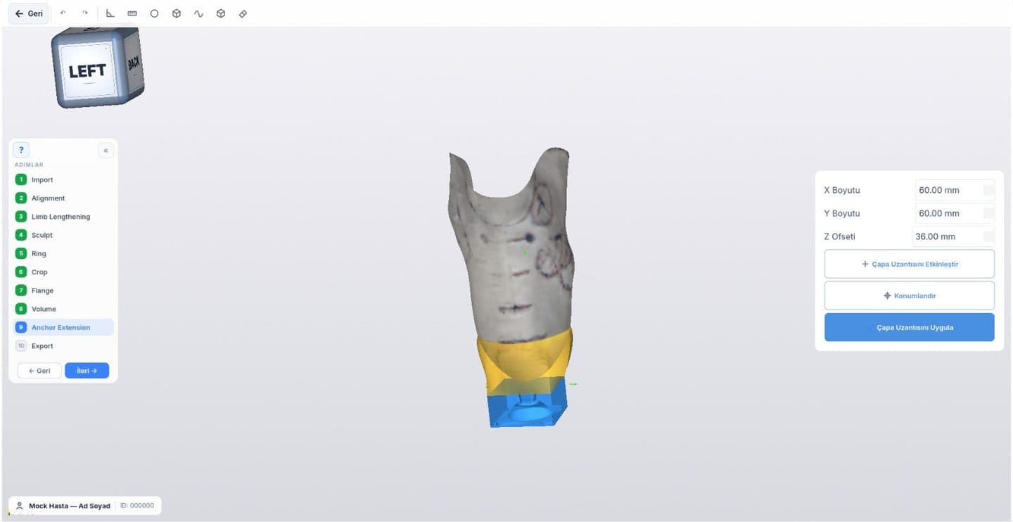
Anchor extension
The attachment block is placed.
- 11
Volume
Volume check.
- 12
Export
File or report.
Upper Extremity
Upper extremity / socket (UE)
Prosthetic socket geometry from transradial and transhumeral residual-limb scans: flange, reduction rings, fine sculpting, and production export.
- 1
Import
Upper extremity residual-limb scan (PLY/STL/OBJ/CPX/VTP) is loaded (transradial / transhumeral).
- 2
Alignment
Model is aligned to anatomical reference axes.
- 3
Crop
Socket boundaries and trimline are cropped.
- 4
Flange
Proximal flange and anatomical transition geometry are built.
- 5
Ring
Stabilization and reduction rings are added.
- 6
Sculpt
Pressure and relief areas are sculpted with a brush.
- 7
Volume
Wall thickness and internal volume are verified.
- 8
Export
Export file or clinical report for diagnostic or definitive socket.
Free measurement tools for this module
Other orthotic and prosthetic design modules
The full scan-to-production workflow: O&P CAD software guide
Try the Socket Design module with your team
Let's run the demo on one of your own cases.