
Protez Soket Tasarımı Modülü (Alt & Üst Ekstremite)
Alt ekstremite (transtibial, transfemoral) ve üst ekstremite (transradial, transhumeral) güdük taramalarından soket tasarlanır: yük alacak ve boşaltılacak bölgeler, flanş ve stabilizasyon halkaları belirlenir, her revizyon önceki sürümleriyle birlikte saklanır. Soket doğrudan 3B yazıcıda basılabilir ya da termoform için frezede işlenecek pozitif model çıkarılabilir. Klinisyen formu onayladıktan sonra üretim dosyası (STL) hazırlanır.
Temel Özellikler
- Yaygın 3B tarayıcılardan alt ve üst ekstremite güdük taraması
- Transtibial, transfemoral, transradial ve transhumeral iş akışları
- Bölgesel yük taşıma ve boşaltma alanları
- Soket formu, flanş, stabilizasyon halkası ve kenar hattı düzenleme
- Doğrudan 3B baskı ya da termoform için frezede işlenecek pozitif model
- Revizyon geçmişi ve sürümleri yan yana karşılaştırma
- Prova soketinden nihai sokete aynı tasarım
- Klinisyen onayı sonrası üretim dosyası (STL)
Alt & üst ekstremite
3B baskı & termoform
Revizyon geçmişi
Hangi klinik problemi çözer
Soket, protezin hastayla temas ettiği tek parçadır; uyum sorunlarının büyük kısmı burada doğar. Geleneksel akışta güdükten alçı negatif alınır, pozitif model dökülür ve model elle düzeltilir: hangi bölgeden ne kadar malzeme alındığı ustanın kararıdır ve hiçbir yere yazılmaz. Bu yüzden altı ay sonra hacim değiştiğinde revizyon, önceki kararın üzerine değil sıfırdan kurulur.
Dijital soket tasarımında güdük geometrisi bir kez taranır ve üzerinde yapılan her değişiklik kayıtlı kalır, sonradan geri dönüp düzenlenebilir. Bir sonraki soket bu kayıtlı geometriyle karşılaştırılarak üretilir.
Güdük taramasından soket geometrisine
Klinisyen güdük taramasını açar ve vakaya göre alt ya da üst ekstremite akışını seçer. Transtibial ve transfemoral alt ekstremite vakalarında yük taşıyıcı ve boşaltma bölgeleri; transradial ve transhumeral üst ekstremite vakalarında proksimal flanş, stabilizasyon halkaları ve anatomik kenar kıvrımları kurgulanır. Tarama eksen boyunca hizalanır, distal uç ve proksimal kenar belirlenir.
Kenar hattı, medial-lateral yükseklikler ve kesim hattı ekranda düzenlenir. Her düzenleme yeni bir sürüm olarak kaydedilir; iki sürüm yan yana karşılaştırılabilir, böylece 'geçen sefer neyi değiştirmiştik' sorusunun cevabı dosyada durur.
Klinisyen onayı bu modülde iki noktada devrededir: bölgesel yük/boşaltma haritasının onaylanması ve nihai formun üretime çıkarılmadan önce onaylanması.
Ürettiği ölçümler ve çıktılar
Modül güdük uzunluğu, seviye seviye çevre ölçüleri ve hacim değerlerini taramadan türetir. İki tarama karşılaştırıldığında hacim değişimi sayıyla görülür; soket değişiminin zamanlaması bu sayıya göre planlanabilir.
Çıktı tarafında prova soketi ve nihai soket için doğrudan 3B baskıya uygun üretim dosyası (STL), termoform atölyeleri için de frezede işlenecek pozitif güdük modeli hazırlanabilir. Provada yaptığınız düzeltme nihai sokete kendiliğinden taşınır. Dosya klinikteki yazıcıya, CNC tezgahına ya da partner üretim merkezine gider.
Lower Extremity
Alt ekstremite / soket (LE)
Transtibial ve transfemoral güdük taramasından protez soketi: yük binen ve boşaltılan alanların şekillendirilmesi, kenar bitişi ve 3B baskı ya da frezede işlenecek pozitif model için üretim dosyası.
- 1
Taramayı Yükle
Tarayıcınızdan aldığınız güdük taramasını yüklersiniz.
- 2
Hizalama
Tarama referans eksenlerine göre hizalanır.
- 3
Uzunluk Ayarı
Soketin kesileceği yüksekliği ve modele eklenecek uzunluğu belirlersiniz.
- 4
Şekillendirme
Yük binecek ve rahatlatılacak bölgeleri tek tek kabartır ya da oyarsınız.
- 5
Daraltma Halkaları
Güdüğün belirli seviyelerinde çevreyi daraltan halkalar eklenir.
- 6
Kesim Hattı
Soketin kesim hattını belirleyip fazlasını kırparsınız.
- 7
Kenarı Dışa Açma
Soket kenarını dışa doğru açıp yumuşatırsınız.
- 8
Kenar Kıvırma
Açık kenarları milimetre hassasiyetinde kıvırırsınız.
- 9
Kalınlık Verme
Soket duvarına et kalınlığı verilir.
- 10
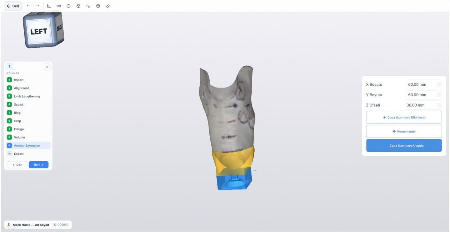
Bağlantı Bloğu
Protez parçalarının bağlanacağı sabitleme bloğunu konumlandırırsınız.
- 11
Hacim
Soketin iç hacmini kontrol edersiniz.
- 12
Dosya ve Rapor
Tasarım, üretim dosyası ya da klinik rapor olarak alınır.
Upper Extremity
Üst ekstremite / soket (UE)
Transradial ve transhumeral güdük taramasından protez soketi: üst kenar (flanş), daraltma halkaları, bası ve rahatlatma alanlarının ince ayarı ve üretim dosyası.
- 1
Taramayı Yükle
Transradial ya da transhumeral güdük taramasını tarayıcınızdan yüklersiniz.
- 2
Hizalama
Tarama anatomik referans eksenlerine göre hizalanır.
- 3
Kesim Hattı
Soketin sınırlarını ve kesim hattını belirleyip fazlasını kırparsınız.
- 4
Üst Kenar (Flanş)
Soketin proksimal kenarı ve anatomiye geçiş bölgesi oluşturulur.
- 5
Daraltma Halkaları
Soketi sabitleyen ve çevreyi daraltan halkalar eklenir.
- 6
Şekillendirme
Bası ve rahatlatma alanlarını ince ayarla şekillendirirsiniz.
- 7
Hacim ve Duvar Kalınlığı
Duvar kalınlığını ve soketin iç hacmini kontrol edersiniz.
- 8
Dosya ve Rapor
Prova soketi ya da nihai soket için üretim dosyası (STL) veya klinik rapor alınır.
Bu modülle ilgili ücretsiz ölçüm araçları
Diğer ortez ve protez tasarım modülleri
Taramadan üretime tüm iş akışı: medikal 3D CAD yazılımı rehberi
Soket Tasarımı modülünü ekibinizle deneyin
Demoyu kendi vakalarınızdan biri üzerinde yapalım.