
AFO (Ankle-Foot Orthosis) Module
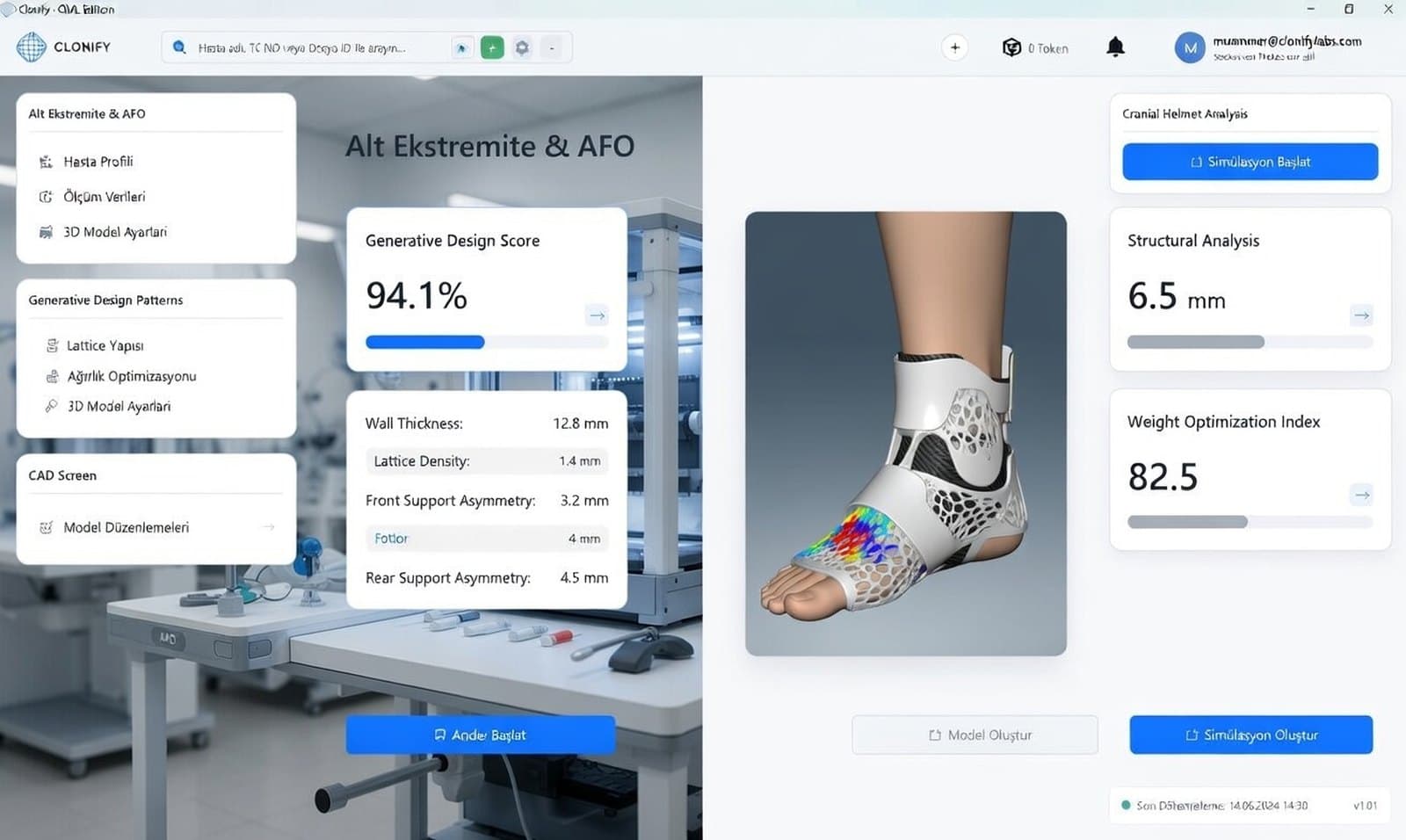
The desktop CAD engine for AFO design is ready and currently undergoing field validation with pilot clinics. The module supports both direct 3D-printed shells (STL/OBJ) and CNC positive milling molds (mold step) for thermoforming workshops: open scan formats (PLY, STL, OBJ, CPX, VTP) are imported, aligned, thickened with strap slots, and exported after clinician approval.
Key Features
- Leg and foot scan import (PLY, STL, OBJ, CPX, VTP)
- Neutral-position alignment and crop
- Regional shell thickness and edge line
- Strap slot and trimline editing
- Direct 3D printing and CNC positive mold for thermoforming
- Production file export after clinician approval
- Versioned revisions from the same scan
Alignment
Shell thickness
Strap slots
The clinical problem it targets
The most labour-intensive steps in AFO fabrication are the casting session, hand-correcting the positive model and grinding the trimline. Holding the foot in a neutral position matters enough that casting is often a two-person job, and with spastic patients it may have to be repeated. Correcting an ill-fitting orthosis means running the whole chain again.
This module aims to replace the plaster chain with a scan-based line: designing repeatedly from one scan, revising without a new casting session, and setting the trimline on screen instead of at the grinder. The desktop CAD engine and steps are ready, with clinical validation underway in pilot clinics.
The planned workflow
The flow is designed around four steps. The leg and foot scan is imported, the foot aligned to a neutral position and unneeded regions cropped. A shell is then derived from the surface, with thickness adjustable per region — the ankle flexes with every step while the heel section has to stay rigid.
In the third step edges are smoothed and strap slots are cut. In the fourth the clinician approves the trimline, the shell thickness and the stiffness distribution. The file is exported after that approval.
Intended measurements and output
On the output side, Clonify supports both manufacturing routes: a direct 3D-printable shell file (STL/OBJ) and a CNC positive milling mold (mold step) for thermoforming workshops. Whether a clinic prints AFOs directly with additive manufacturing or modernizes its vacuum thermoforming line using CNC milled molds, it uses the same parametric workflow.
On the measurement side, scan-derived values such as foot length, ankle circumference, and calf circumference are saved in the case file, enabling objective revision tracking.
AFO workspace: from scan to export
The limb on screen is a sample scan file (afo_limb_orig.ply). The steps match the AFO 3D-print workflow in the desktop app.
- 1Import
- 2Align
- 3Grow
- 4Export
Drag to rotate the model · Stages advance as you scroll
01 · Import
Import
The lower-leg scan is loaded. The CNC line is a separate mold flow; this view is the 3D-print path.
- Workspace
- AFO
- Step
- Import
Real sample scan: afo_limb_orig.ply — no identifying data
1. Import — Import
The lower-leg scan is loaded. The CNC line is a separate mold flow; this view is the 3D-print path.
2. Align — Alignment and foot direction
The model is seated on the reference axes; foot/toe orientation is adjusted on the scan.
3. Grow — Thicken, flare and straps
The surface is thickened, edges are flared, strap slots and holes are cut. The shell is offset from the scan surface.
4. Export — Volume and export
After the volume check the model leaves as a file or a report.
AFO
AFO (3D-print & CNC mold line)
Two production routes for the AFO: a shell for direct 3D printing, or a CNC positive mold for thermoforming workshops.
- 1
Import
Leg and foot scan (PLY/STL/OBJ/CPX/VTP) is loaded.
- 2
Alignment
The model is aligned to the reference axes.
- 3
Toe rotation
Foot/toe orientation is adjusted on the scan.
- 4
Toe cap
Toe-cap geometry is added.
- 5
Crop
Unwanted regions are cropped.
- 6
Sculpt
The surface is raised or carved with a brush.
- 7
Grow
The surface is thickened into a solid.
- 8
Edge flare
Edges are flared outward and softened.
- 9
Strap slot
Strap channels are cut.
- 10
Holes
Ventilation / connection holes.
- 11
Volume
Volume and thickness check.
- 12
Export
The finished model is exported as a file or report.
Free measurement tools for this module
Other orthotic and prosthetic design modules
The full scan-to-production workflow: O&P CAD software guide
Try the AFO module with your team
Let's run the demo on one of your own cases.